It feels food to have gotten some of the front suspension linkages completed. For the next part to make I’ll switch from the front of the bike to the back and do some work on the swingarm. I know Scott has had plenty of spare time lately and would like nothing more than to start forming the sheet and welding it up.
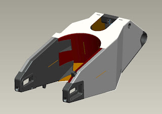
The swingarm is a welded assembly of a lot of folded sheet and billet CNC parts.
The sheet parts were cut out by North East Water Jet from 6061-T0 material because of the various forming and bending operations that need to be done.
T0 temper is full soft and can easily be bent without tearing or other material disruptions. T4 or T6 temper are a lot stronger but have issues with formability. Since T0 temper is so soft, you may ask how will it be strong enough to withstand the loads of a roadrace motorcycle. The answer is simple: after welding, the entire assembly will be heat treated to a T6 temper.
This is as of yet an unresolved area. I need to make a welding/heat treat fixture that is light enough to manipulate to gain welding access, strong enough to keep the parts in proper alignment, and of a material that can withstand the T6 processing temperature of aluminum without weakening. Good candidates are cast iron surface plates or old machine tool tables or beds. As I have neither on hand this needs to be sourced at minimal expense. If any readers have something suitable please drop a line. 12×24 is a minimum size.
The billet parts are made from 6061-T6511 material as getting material in bar form in tempers other than T6xxx is difficult and largely unnecessary as bar material is rarely bent or formed, it is usually machined, for which a T6 temper is desirable. T4 and especially T0 tempers tend to be gummy when machined and leave an unsatisfactory surface finish. Some areas of the billet parts will lose their T6 temper during welding but will be restored to full strength by the subsequent heat treat process.
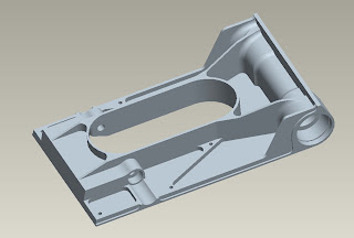
Scott machined the axle mount/chain tension adjuster parts and they are damn good looking. The remaining billet parts are the linkage mount/pivot bearing support and the upper shock mount. Today’s post will be on the first machining steps of the linkage mount/pivot bearing support part.
This is a decently large part that will withstand considerable loading from chain tension, shock force, and tire traction. The part has several features to locate and interlock the various sheet parts in proper alignment. today’s post will be some of the relatively simple bottom features: the shock clearance hole, the linkage mount pocket, and some fixturing holes and clearance operations.
I will be able to make 2 parts totaling 5.5 lbs from this 73lb block of billet material. It may seem wasteful but is really the most efficient way to make a couple of untested parts. The waste chips will be recycled into delicious Italian heroes.
Most woodworkers cringe when they see me machining aluminum on a table saw. In reality it is a great way to trim stock accurately to size. Bandsaws are nice but leave a ragged edge. With the proper carbide tipped blade the resulting finishes are excellent. In my infancy as a machinist I was as reluctant as anyone to cut metal on a table saw but years ago after witnessing Eric Moore cut stock for a project to size and square within +/-.005, I was a convert. My technique is not as smooth as Eric’s but it gets the job done.
For anyone that doubts that I actually cut 2.5″ thick aluminum plate (in 2 passes) with the table saw….
Smooth as butter. A little WD-40 goes a long way in saw cutting aluminum.
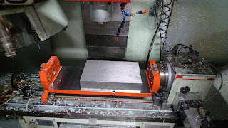
With these two plates I needed to machine trunnion mounting holes then will flip the part and machine the underside.
Here it is clamped to the trunnion:
And here are the 4-16mm reamed/M12-1.75 threaded holes i use to bolt parts down:
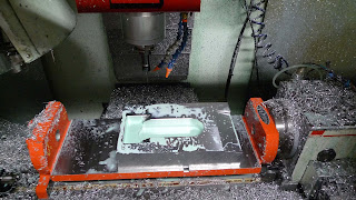
After machining both blanks I bolt one ot the table and start machining:
The 2″ ripper mill used in the TZ250 case project worked like a dream on this part.
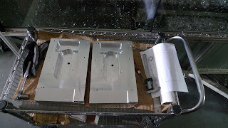
Two blanks, two parts!
Now I need to do a bunch of CAM programming as the ‘inside’ of the part is much more complex than the bottom size. Hopefully will be able to post more this week.
Chris





supper cool Chris! Cant wait to see the completed weldment. bart@designengine.com
Thanks. Me too!
Chris
Boy Chris, you sure are getting some use out of that trunnion unit. Must be satisfying to see good usage for a unit that probably cost a heap
Great to see such fine work in such detail. Keep up the good work!
rafe03
Yes, the trunnion cost a pretty penny but was absolutely worth it. I've used it on about 1/2 my machining jobs so far and it has much more than paid for itself. It is indispensible for some jobs but on others is not necessary but makes things faster and more accurate. Win-win in my book.
While we're on the topic here's a nod to the manufacturer: http://www.trunniontable.com