

All right, its been a while but sometimes life gets in the way of things you want to do. I have been making progress and documenting it, so the next week or so will catch up to the actual state of the build.
We left off with the crankshaft and counterbalance shaft finished with their lathe operations. Next step is to bolt them in the mill and do some 3 and 4 axis machining to generate the crank counterweights, rod throw, and counterbalance weight mounting pad.
The first step for the crank was to sit it on end in some soft jaws and hog out most of the perimeter of the counterweight profile.
Boring the soft jaws: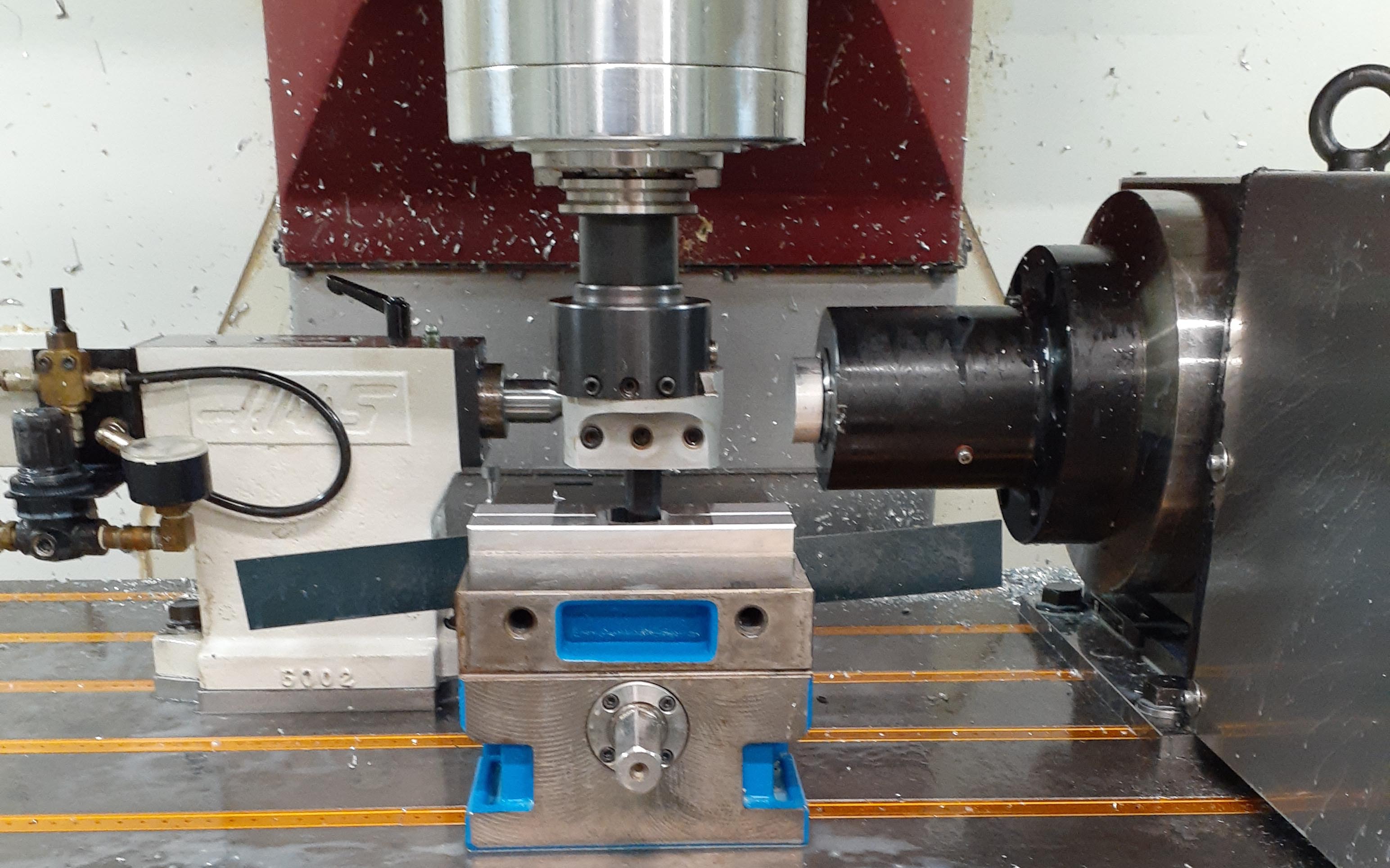 Clamp the part in and load the 5 flute insert mill on an extended shell mill holder……
 Go have lunch, then come back for…..
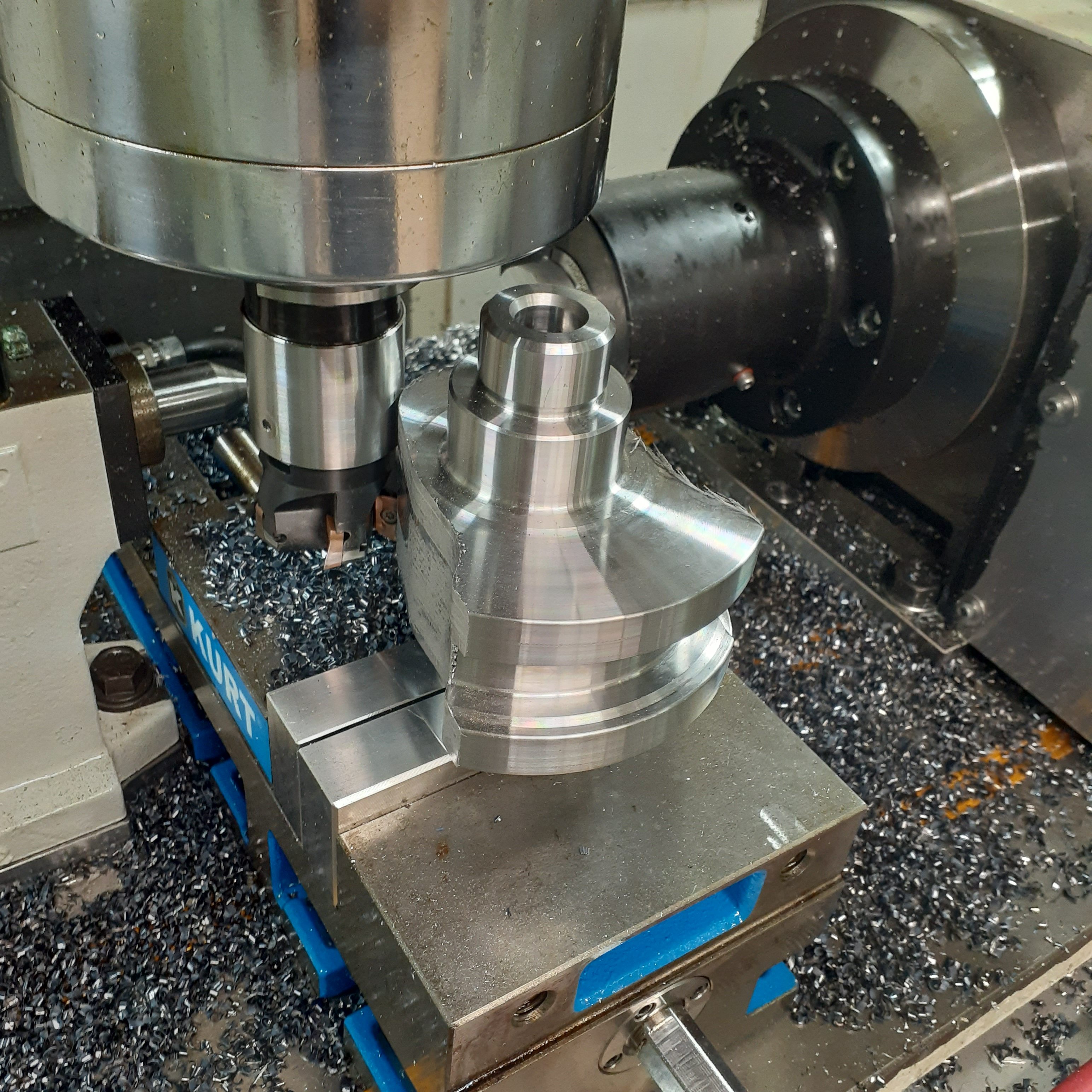 Then a few more operations for the tungsten weight holes and retaining ring grooves and the drilled and reamed lightening hole in the conrod throw.
 Repeat 2x more, then we ca move on to the 4 axis machining for the rod journal roughing.
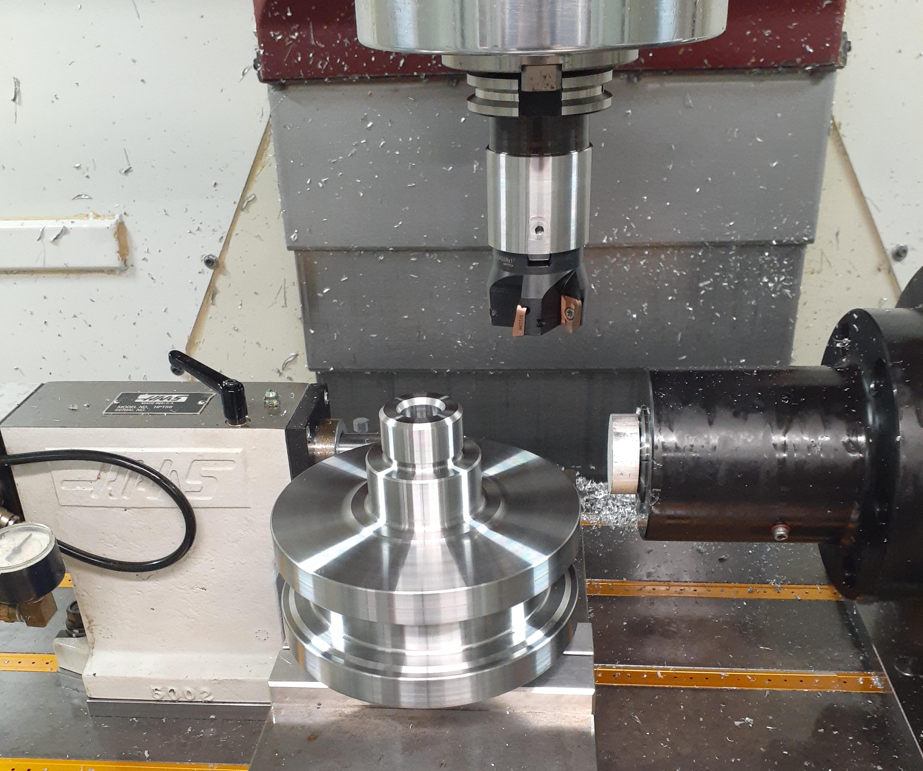
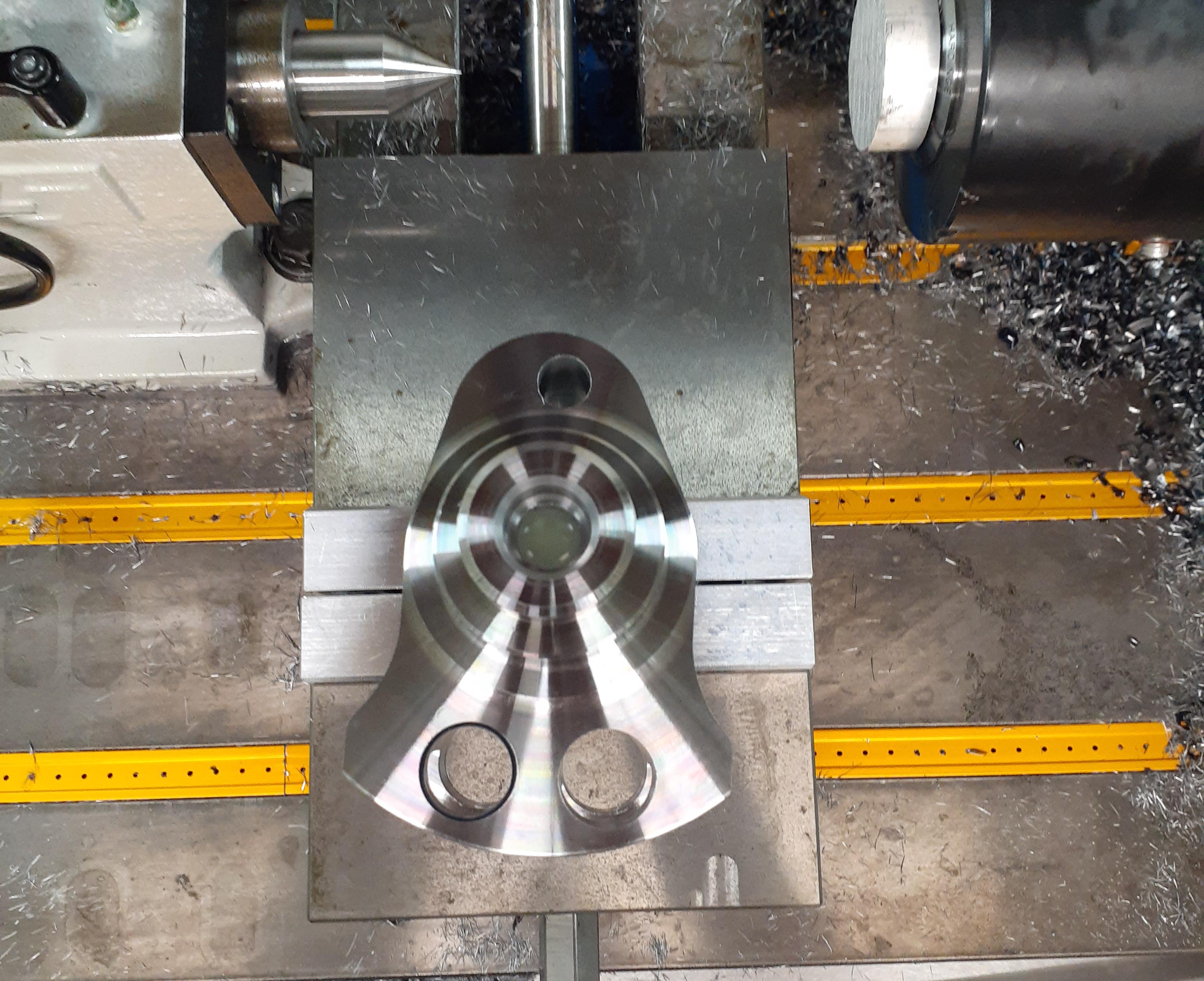
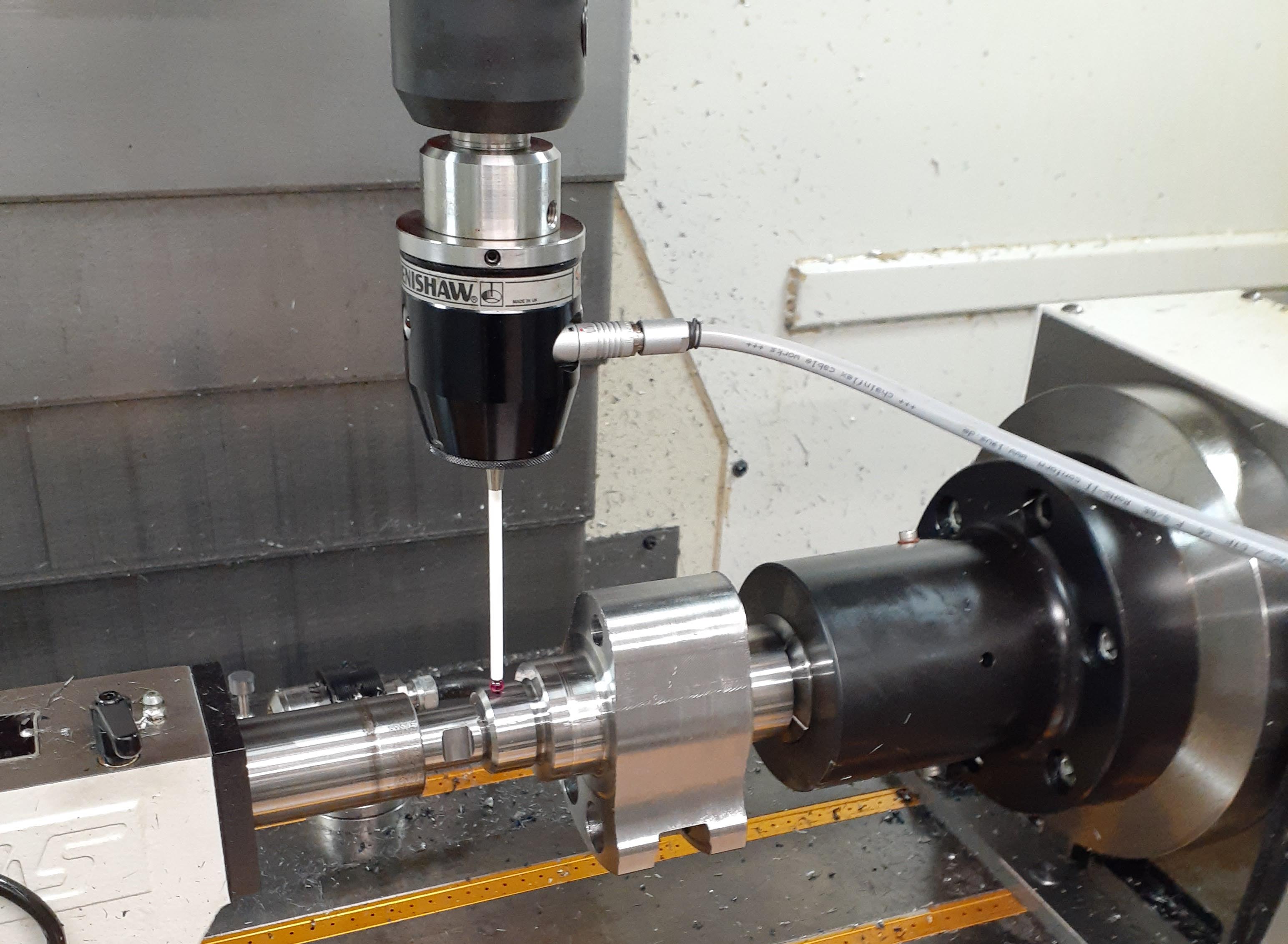
For this step, the crank was mounted in the rotary spindle in a 16C collet with the pneumatic tailstock for outboard support. I used the Ranishaw probe to get an accurate reading on the part zero position.
 And behing all that coolant is the time lapse of the rod throw machining steps:
Next up was the counterbalance shaft, which only needed the mounting pad and holes machined for the tungsten counterweight.
Repeat a few more times for good measure and then moce on to the next setup, drilling the oil holes.
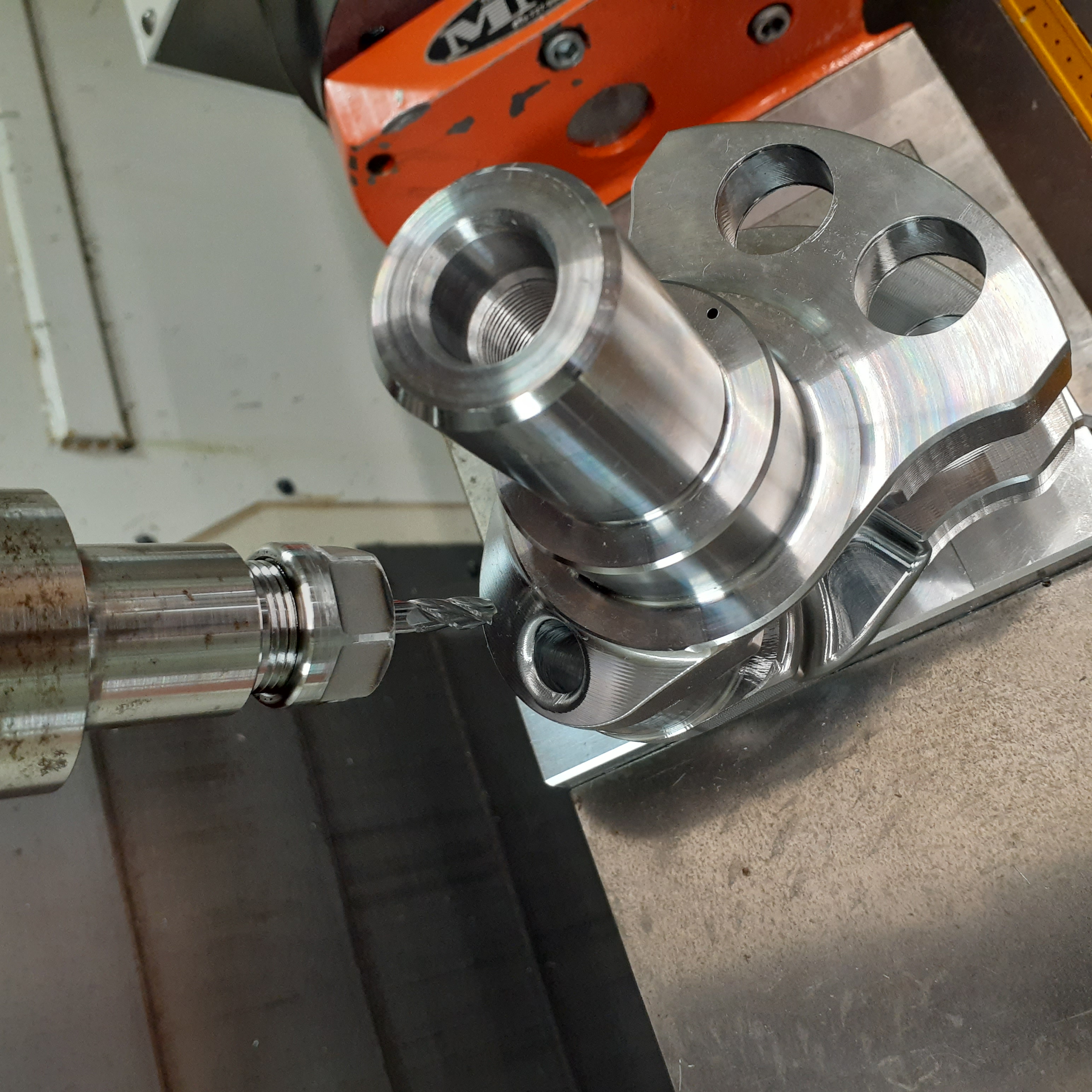
For this, we went back to a soft jaw setup in the vise, but this time on the trunnion table for that extra angular positioning flexibility.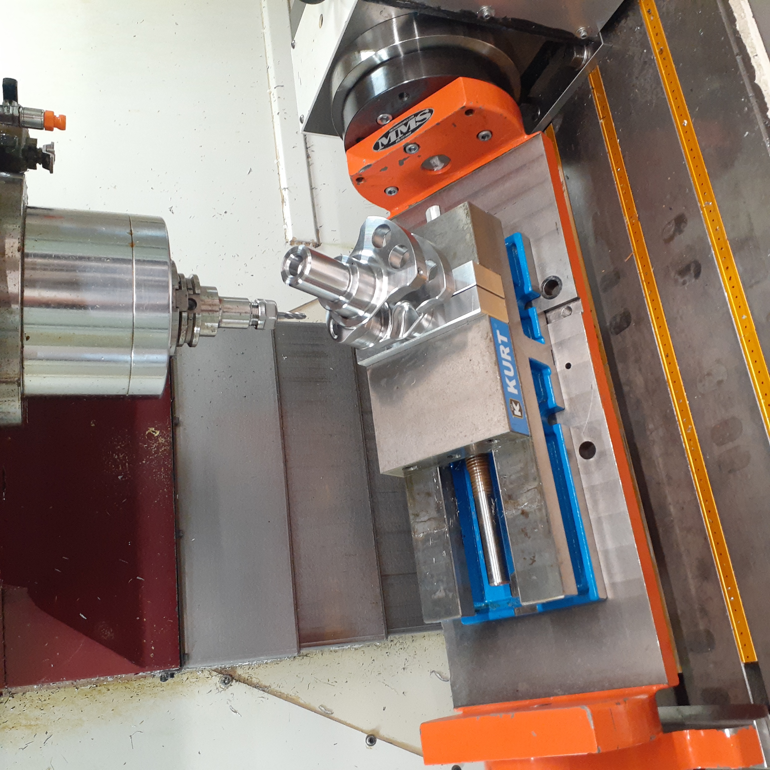 I used a hole for the tungsten weight to match with a hole in the softjaws for accurate clamping orientation of the part in the vise. Then some spotting, drilling, reaming, and counterboring and the oil galley is in position.
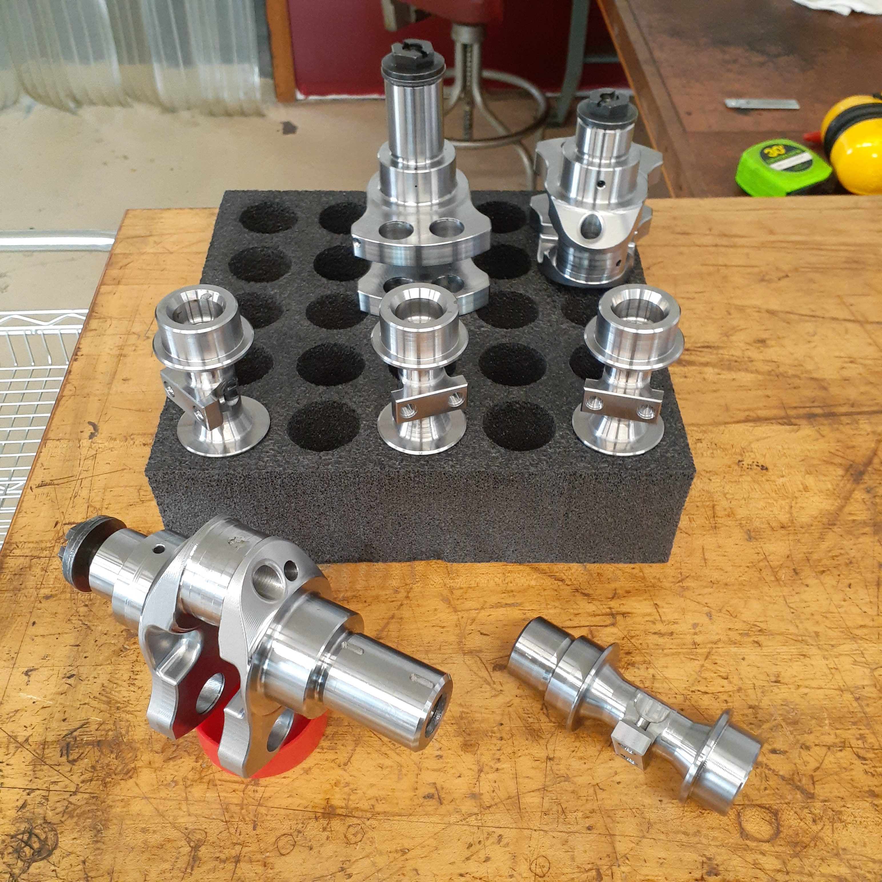
 With the various operations, I ended up wth 3 sets of useable parts. I had one balance shaft that was almost useable but will be a good setup part for the next processing steps.
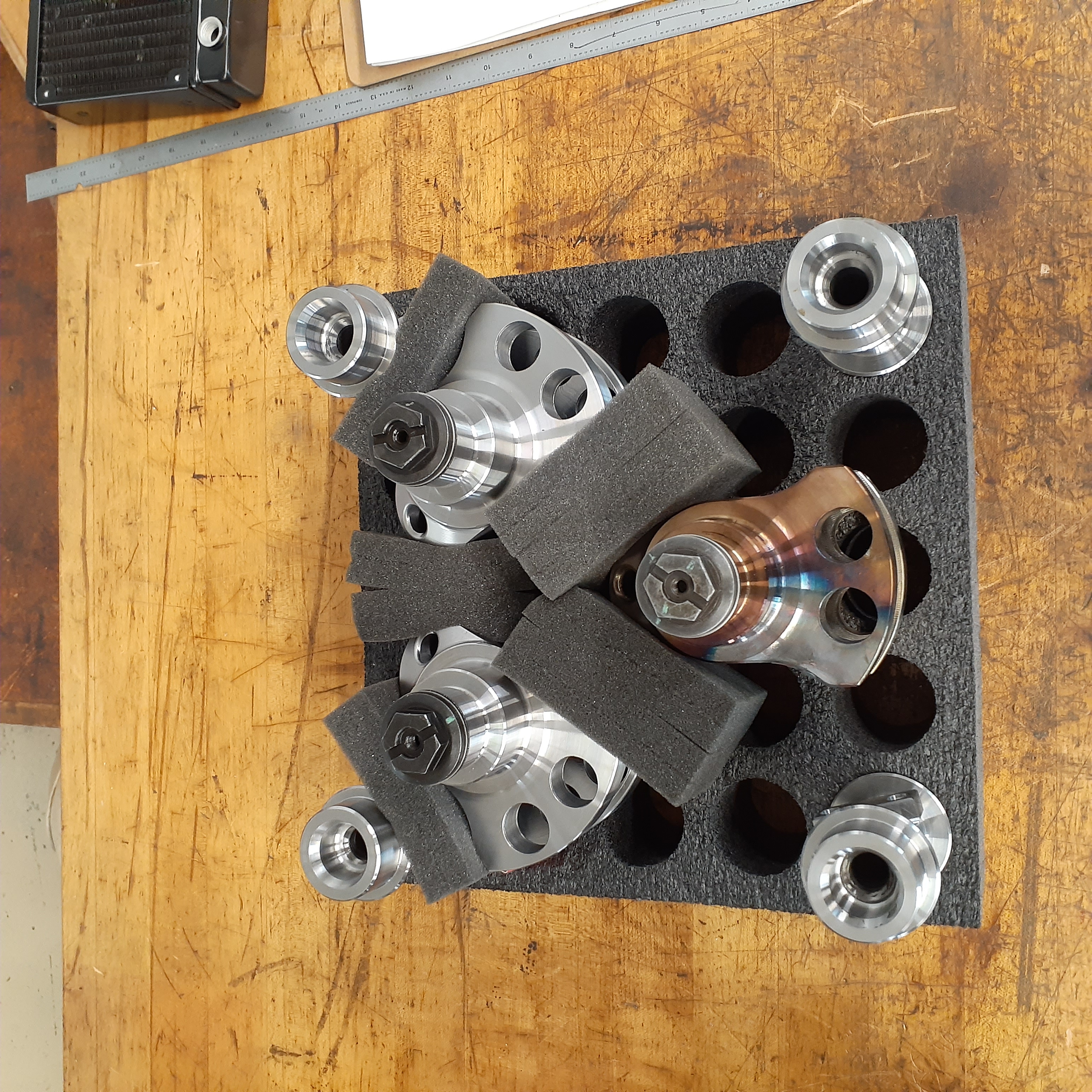 I packed the parts up and shipped them off to Winberg Crankshafts, the final vendor that agreed to do all the finishing and TLC operations on my crank blanks. They do a lot of high level racing work both here in the US and internationally, and will be sure to take the best care of my parts.
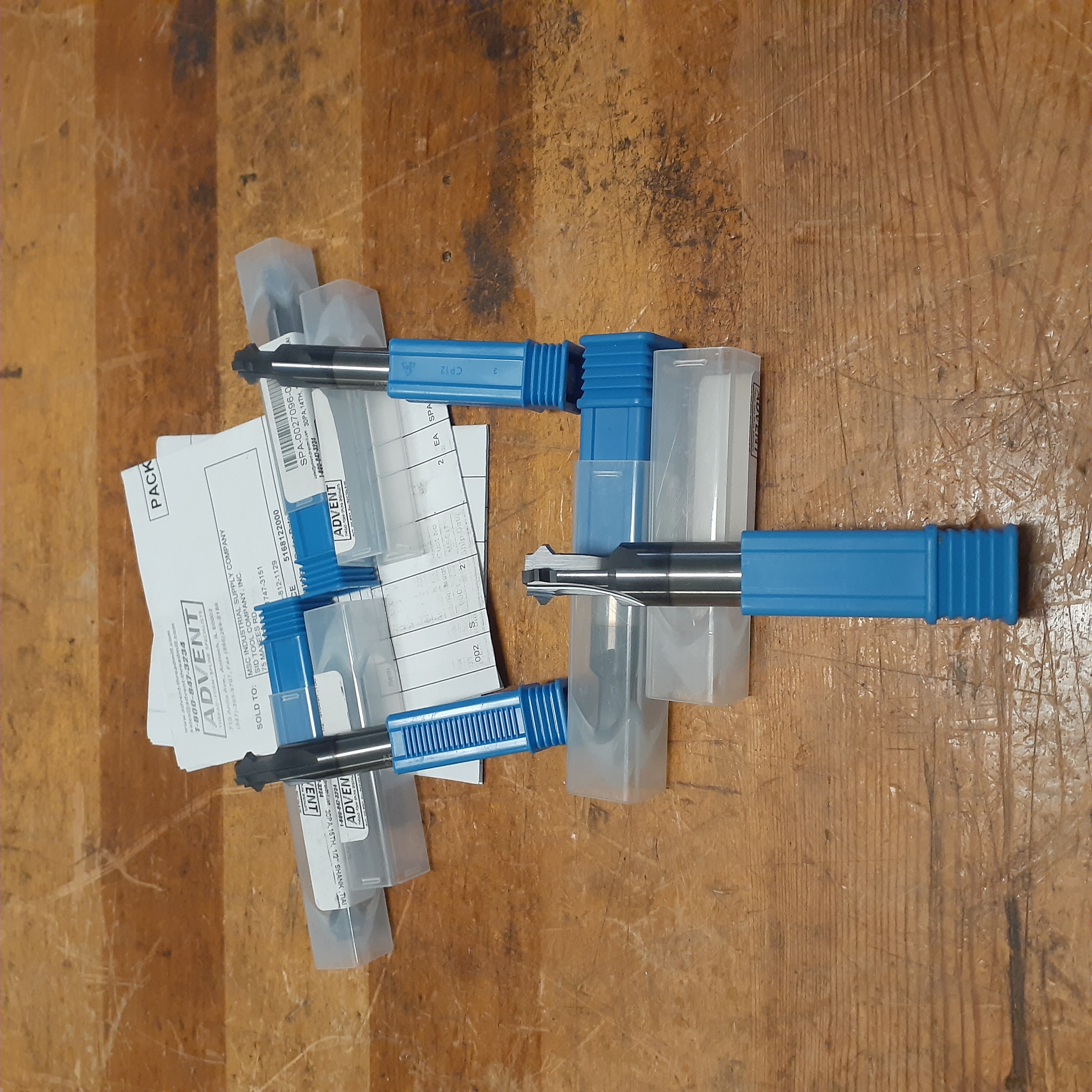
Winberg will grind all the bearing journals to the specified dimensions then return them to me. I will then machine the crank and balance shaft drive splines in a similar collet setup as the rod roughing. I had custom solid carbide form cutters made by Advent Tool and Manufacturing. They reverse engineerd the existing parts and made cutters to reproduce the geometry.
Once they are returned to Winberg, they will do some small detail work, plasma nitride and then superfinish all the parts, at which point they will finally be ready for use.
Yes, there is some heat discoloration on one of the cranks. A small programming error (small with the angular error, not the amount of material removed) reaulted in some material removal where it hsould not have been removed. Since the error was in a non-stressed ares, after consulting the various internet authorities I decided to repair it instead of scrapping it. I then proceeded to create a clean pocket in the offending area, machine a mating plug from matching material, heat both parts to 500F, carefully weld with 4340 welding rod, then let slowly cool in a pot full of sand. The welds were clean with no indication of cracking so it should be a useable part. Winberg will let me know.
