

For this post I’m moving from making parts, to making parts that will help me make parts, if you catch my drift.
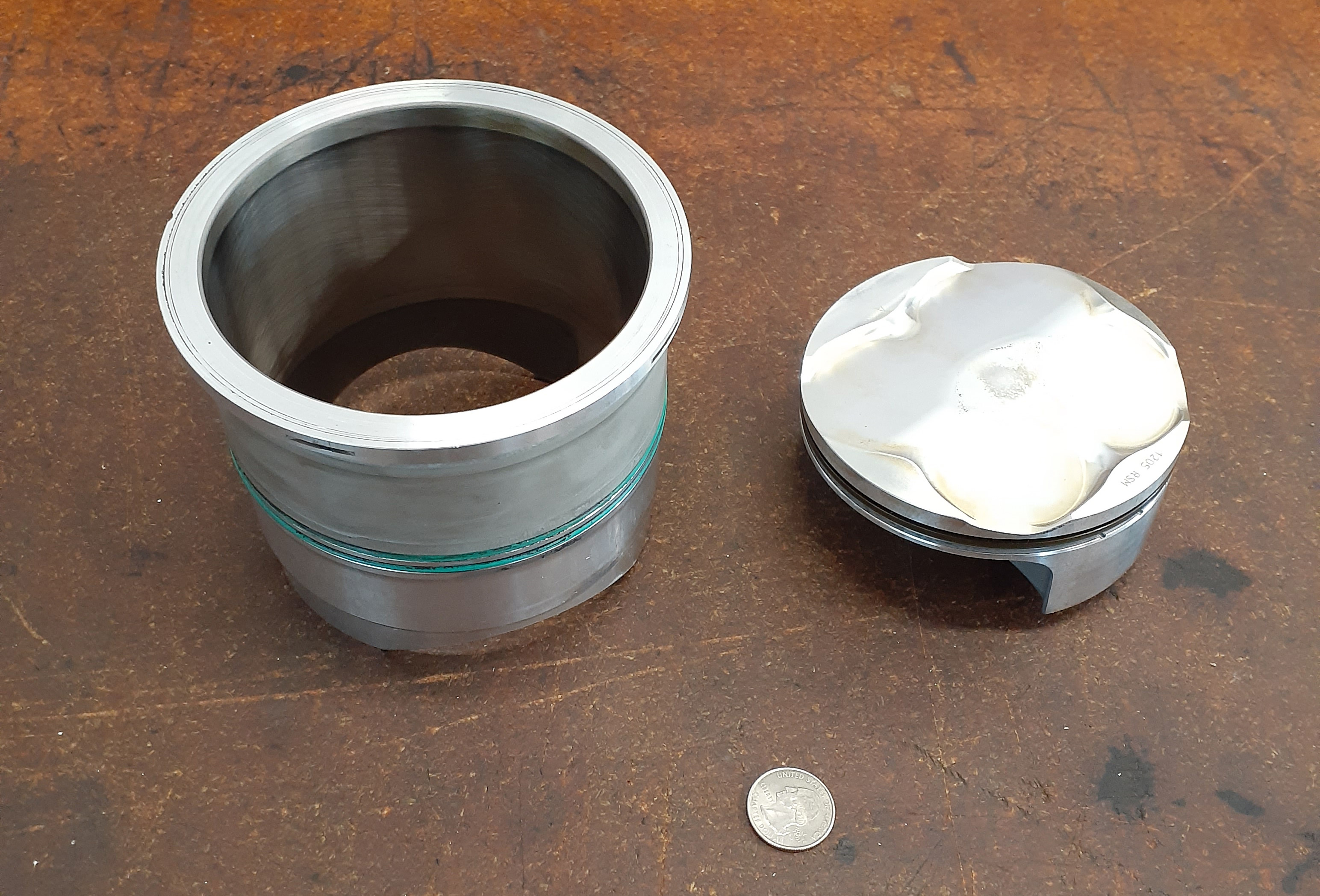
One of the few assemblies that I am using unchanged* is the piston and liner. There’s a lot of engineering behind those parts and since I am using the matching cylinder head, there was no reason to try to do something new here.
 So, if I cannot easily improve the parts, what I can do is be sure they are located precisely and rigidly to ensure minimal losses. An old engine builder from my youth in Staten Island told me that you make power above the cylinder head gasket and lose power below it. What he meant is that the components that decide how much power the engine can potentially make: the intake, combustion chamber, exhaust, and cams, are all usually located above the cylinder head gasket. The components ‘below’ the head gasket: rings/cylinder, and the crank and transmission assembly, can only contribute to a powerful engine by losing as little power to friction and misalignment as possible.
So, to lose as little power as possible, I have to locate this large, relatively flexible cylinder liner in my machined crankcases accurately and rigidly so that whatever combustion pressure is generated, as much as possible goes to turning the rear wheel. This same thought process is embedded throughout the design, from the longer rod to the offset cylinder and down into every component of the engine.
How these issues concern this post is the question’ how to machine an accurate stepped hole?’. The OEM liner has o-rings in two locations, on two different diameters, to seal the water cooling passage. This requires two precisely machined and concentric bores, with a blended step between them so that the first set of orings do not get damaged as they side past it during assembly. Using circular interpolation on a mill is a quick and easy to get a round hole, but unfortunately it is usually not really really round, and because you are cutting with the side of a fluted tool, up close the surface is a series of crests and troughs and along the length there are dimensional changes due to the deflection of the spindle/toolholder/tool. This image grabbed from Harvey Tool shows the situation.
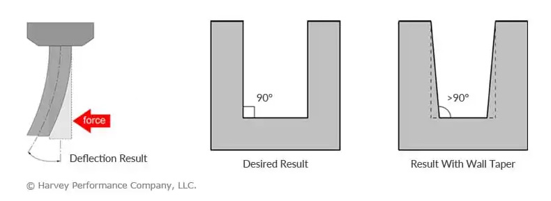 So, with circular interpolation you end up with a mostly round, slightly tapered hole. This makes it difficult to get the surface finish required for reliable sealing with o-rings. Leaky water passages is a feature I definitely don’t want, so a better approach is needed, in this case, easy, bore it. Twice. With a 2 boring bars of a very close cutting dimension. Or if you ony have one, set it twice per part, which when making multiple parts is far from optimum. I like to set tools and forget them until they cut out of spec.
The answer is to make a two cutter boring head, actually much easier than it sounds. With single point cutting tools like boring bars, there is no such thing as cutting eccentrically or aligning multiple cutting tips, so fabricating one is not a practice in extreme accuracy.
My approach was to take an off-the-shelf CAT40 blank from Fitz Rite, and mate it with two CNMG boring bars from Mari Tool.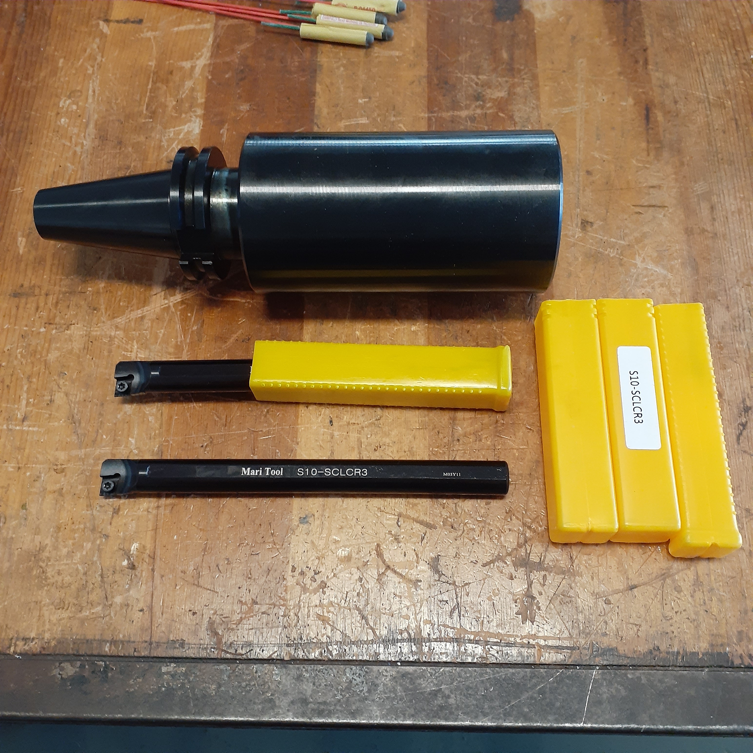
Working it up in CAD was pretty quick.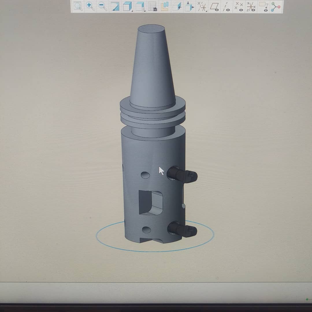 Then it was off the the Bridgeport for some manual handwheel spinning and center, drill, ream for the boring bar mounting holes. some 5/16-18 set screws to lock it in position and a couple of surplus 6-80 threaded adjusters for making repeatable cutting diameter changes.
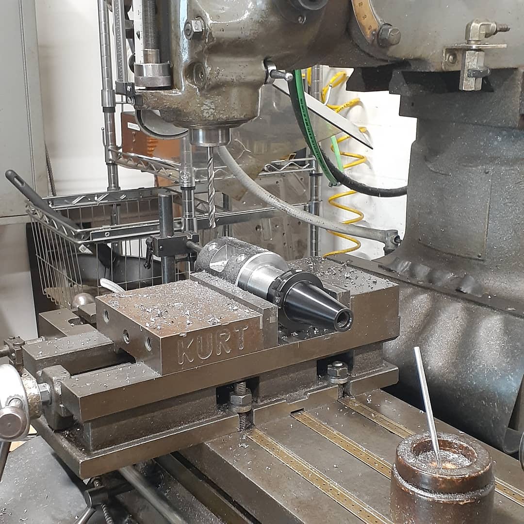 The shorten the boring bars to fit crossways inside the bore.
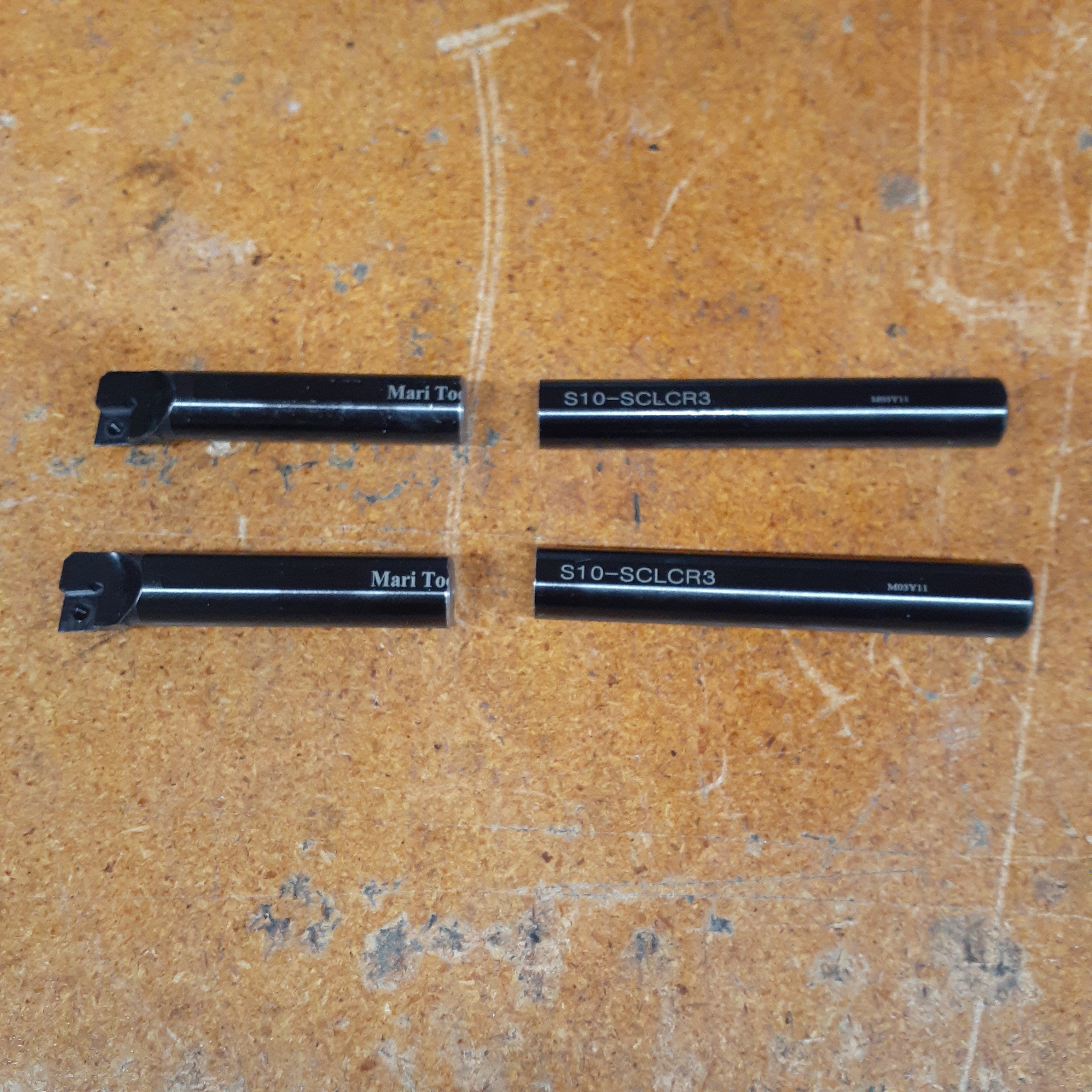 Then assemble it all together and see how out of balance it is. Not much is the answer. Because of the large cutting diameter it will only be spinning about 1000rpm, so a really accurate balance is not necessary.
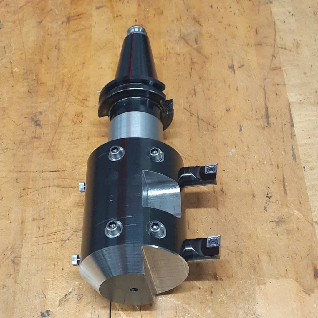
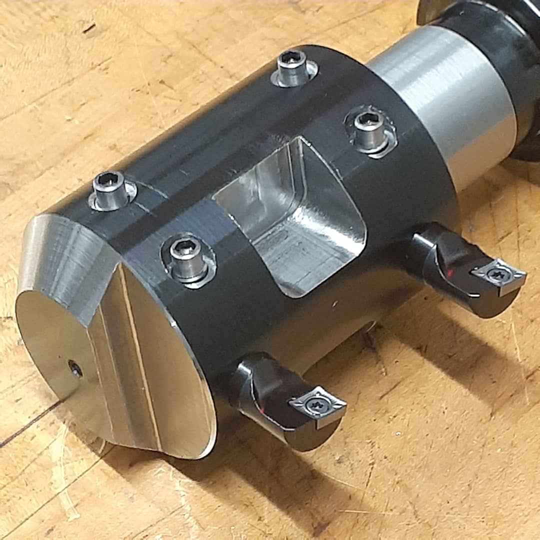
 This assembly will make machining the bore a breeze. The insert angle will create a smoothly tapered step between the diameters and using a relatively large cutter nose radius will ensure a spectacular surface finish, the point of this entire exercise. When machining the cases gets closer I’ll set the cutting diameters using a simple thin plate but for now this is enough progress to move to the next parts.
*Unchanged: Well, mostly unchanged. I do have to machine a small rectangular notch at the base to clear the counterbalance shaft weight. Well, things are tight in there! The notch is far below where the rings traverse so will not affect the functionality of the part. I think.

Nice idea.
Great tooling idea.
Thanks!