

OK, back to making actual parts. Next up is the right side engine cover, which is a little more complex than the left side cover. The right side cover has outboard mount for the generator stator, some stator wire management, mounting and sealing face for the clutch access cap. Oh, it also has the excellent ‘Cosentino Engineering’ logo machined on the stator area.
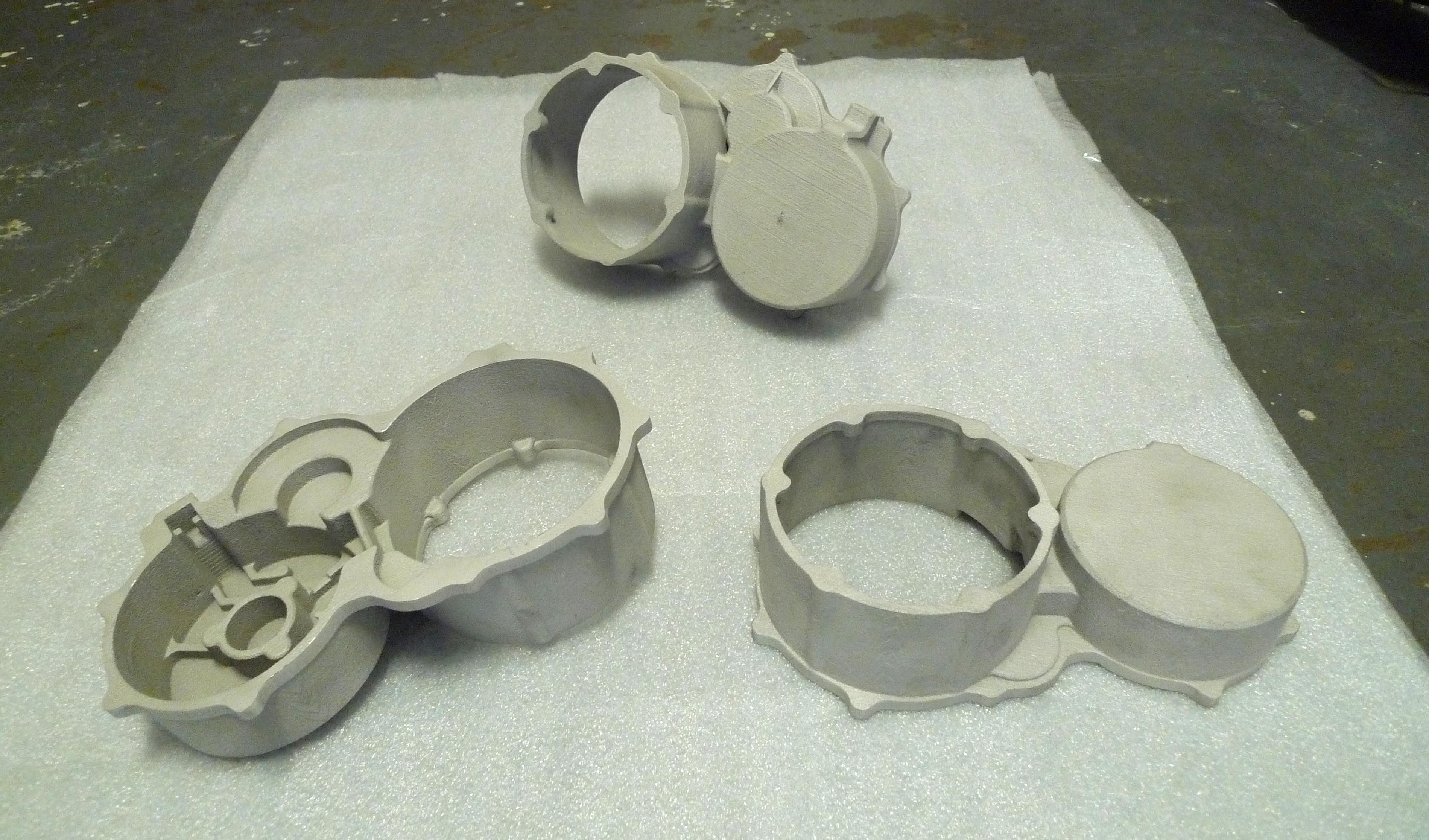 Due to the threading required from both sides, clutch cap on one side, stator mount on the other, this part could never be tried as a single operation. In this case, the first operation was chosen to be the clutch cap side, made simpler by the very flat opposite cast surface that could be used for clamping. 3 dowel pins around the perimeter located the part in place and some clamping screws were used to hold it down.
 Machining was done dry and again resulted in an excellent surface finish. The threaded clutch cap holes were threaded for Time-sert inserts.
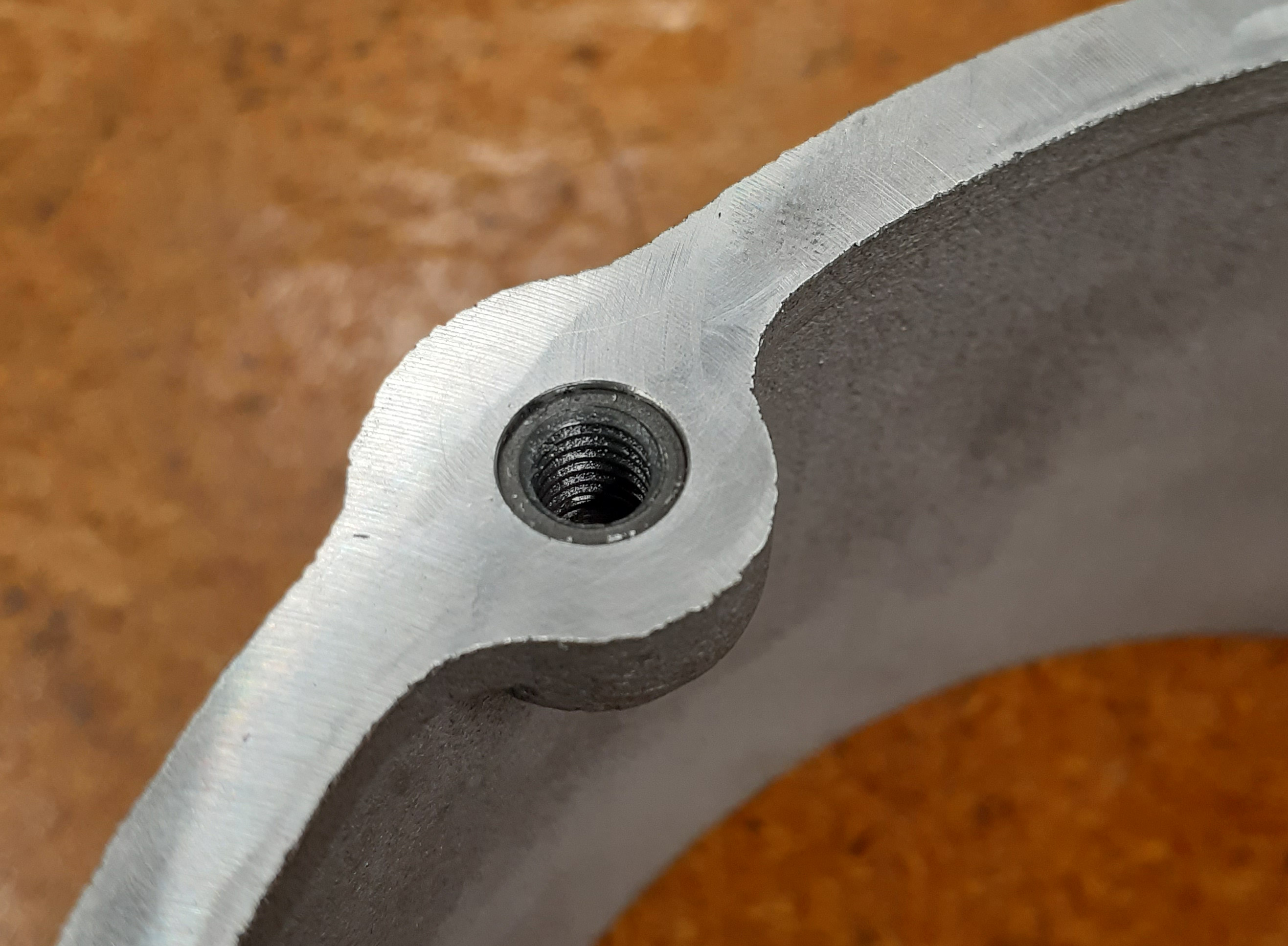 These are flanged, solid thread inserts (not wire like Helicoils) with a synchronized inside and outside thread for a thin wall section. The flange is a nice feature to positively lock the insert in place when tightening and loosening the screw. The thin wall gives the user two options, design with a small boss diameter, or use a normal boss diameter, and if anything ever goes wrong with the thread, you can drill it out and install a Keensert, which have thicker wall section. I chose the latter option, this is a racebike and you never know what will happen, so having the ability to easily create a new thread is a good backup.
I used a spare cutoff from the runner system to do some insert testing. As expected, threading a screw directly into the magnesium produces a soft, easily stripped thread. Using a Time-sert, I was able to strip the allen head socket on a M6 button head screw without damaging the threads. This was good enough for me to stop testing there with the thin wall inserts, as if you are stripping your bolt heads, you are tightening too much.
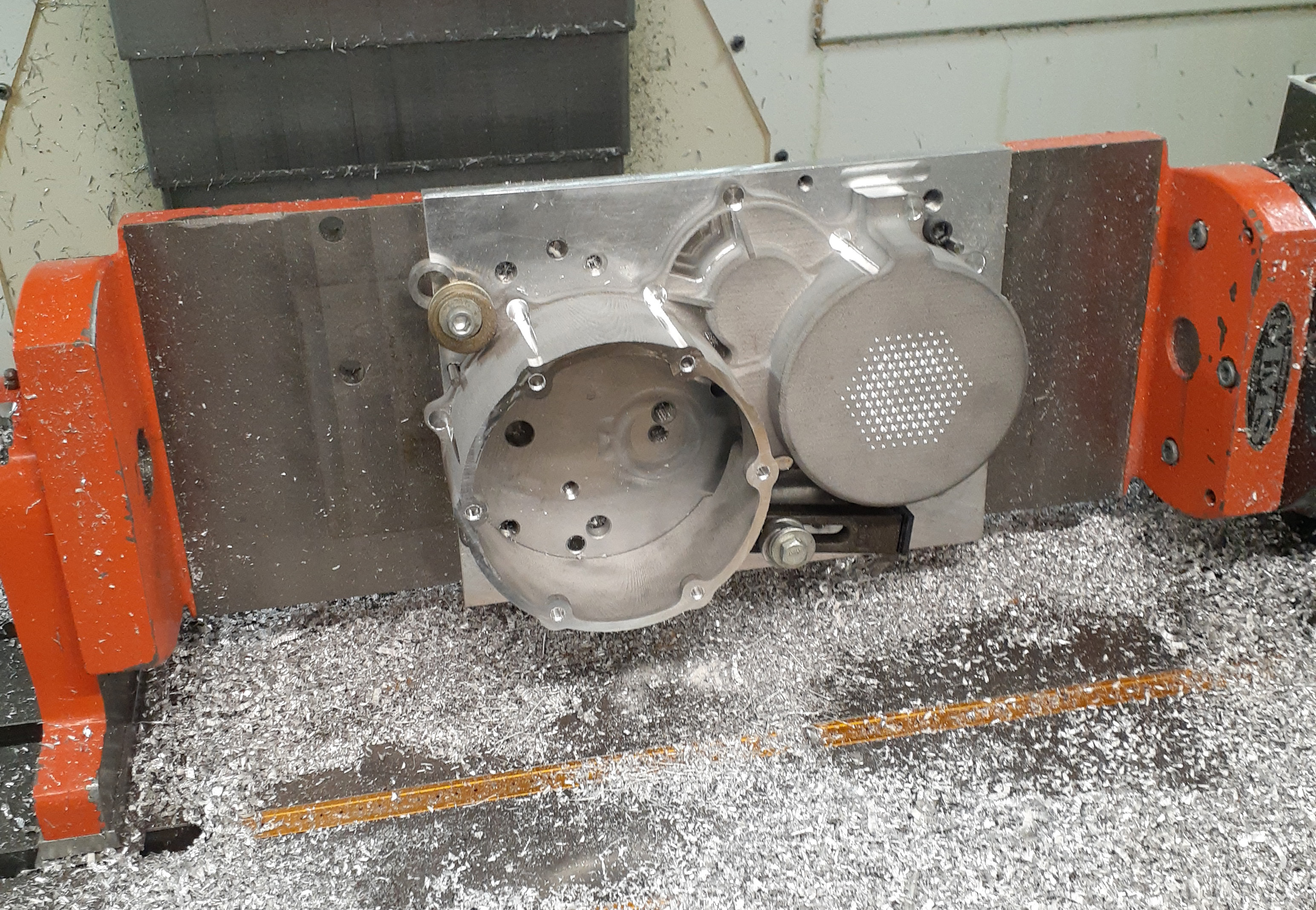
 After these inserts were installed, the part was bolted upside-down onto a matching pattern in the baseplate. A jack screw under the stator area and a little outboard toe clamp was all that was needed for the second machining operation for the main gasket surface and stator mounting and wire management features.
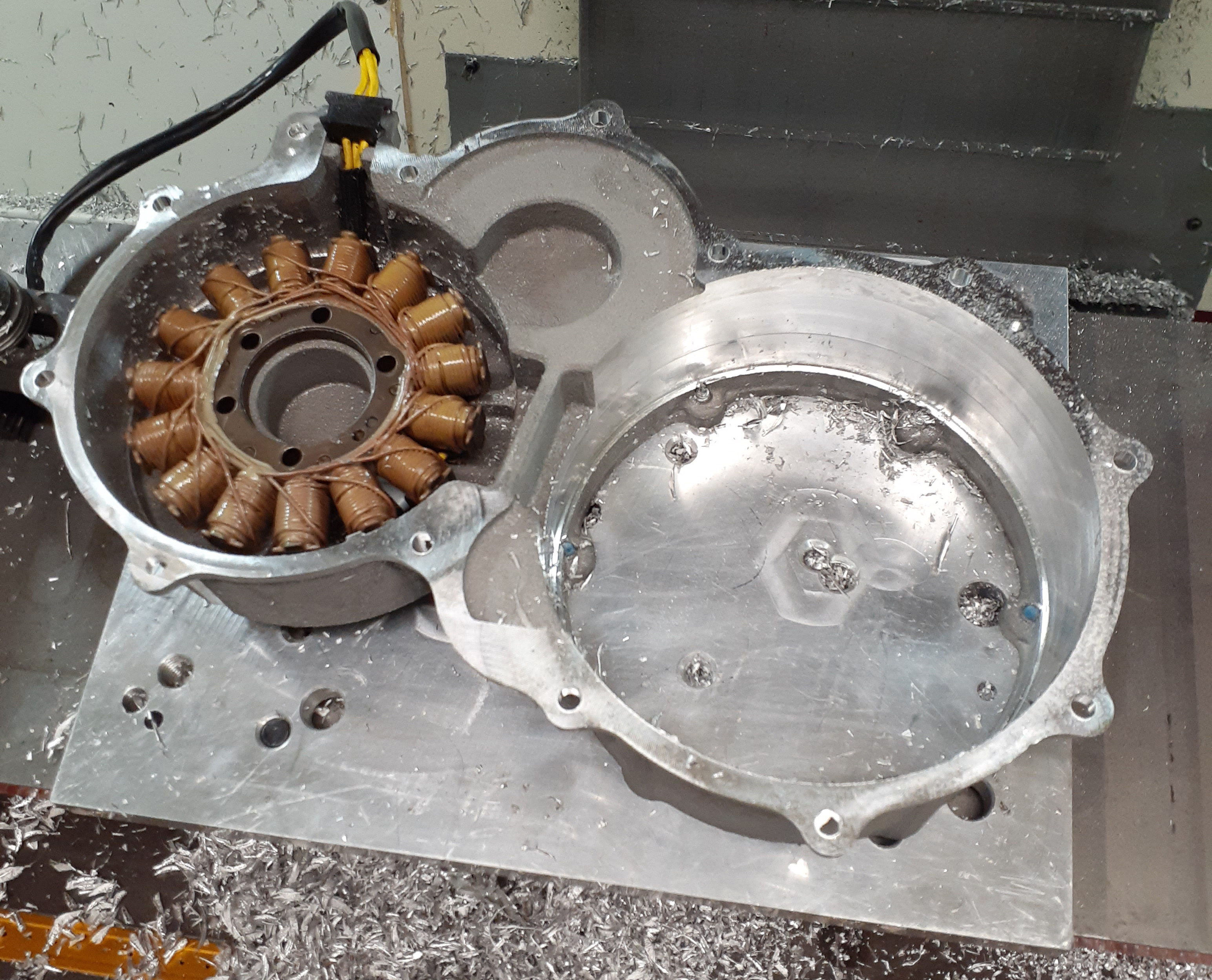 I also did a cleanup pass on the inside surfaces where the clutch basket and the generator rotor are spinning. Besides the extra little clearance, a rough as-cast surface would hold a lot more oil and create more aero/hydro drag than a cleanly machined surface. An angled ‘wiper’ is included to channel the flung oil downwards and into the sump area. Every little bit helps! Unfortunately, I do not have a clear image of this second clamping setup, but it worked fine, and a quick fit check of the stator and wiring was successful.
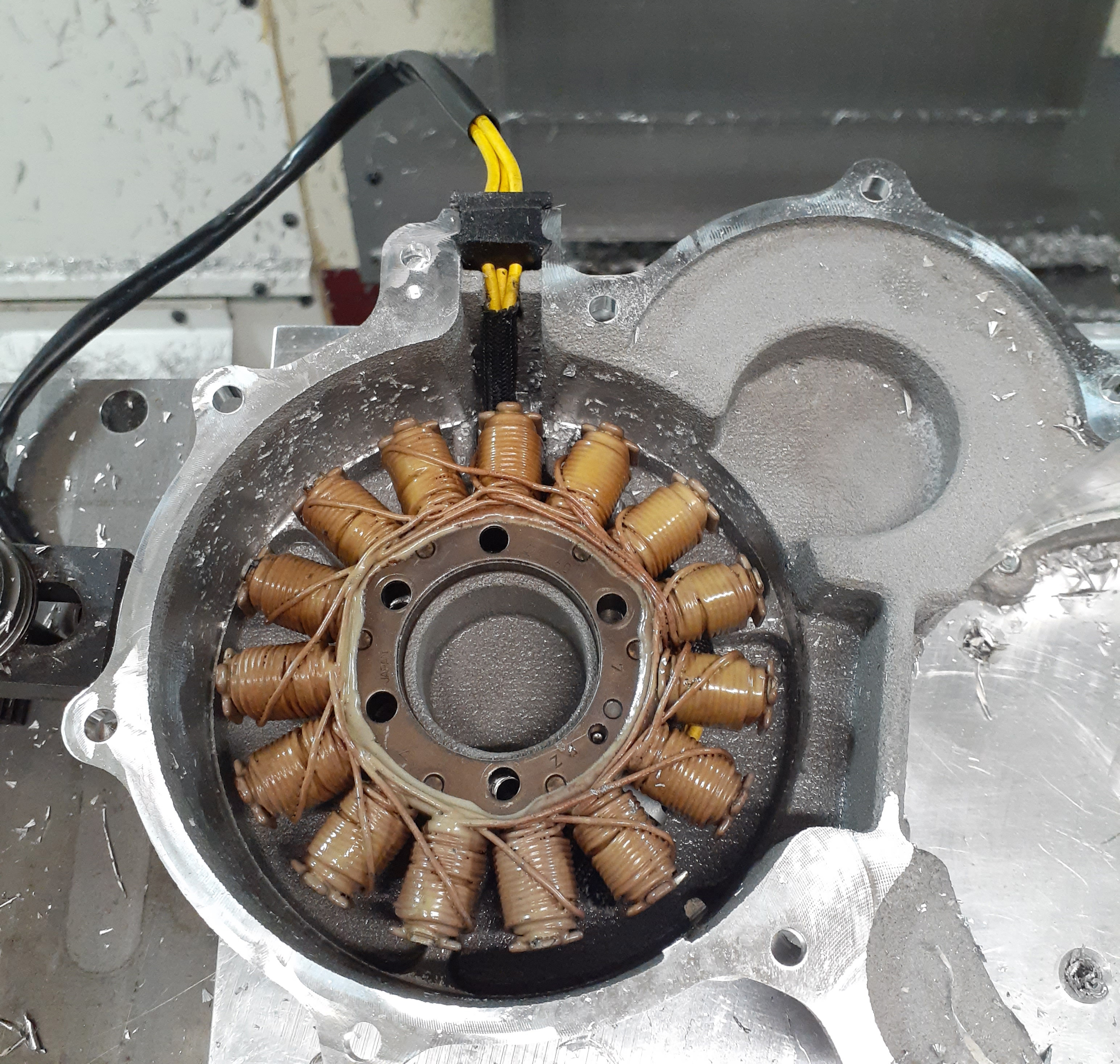 I included a small cast channel for the stator wire and with the Martin trunnion table rotated 90 degrees, machined a notch to use the OEM rubber seal on the stator harness. This will keep things nice and oil-tight without gobs of messy sealant.
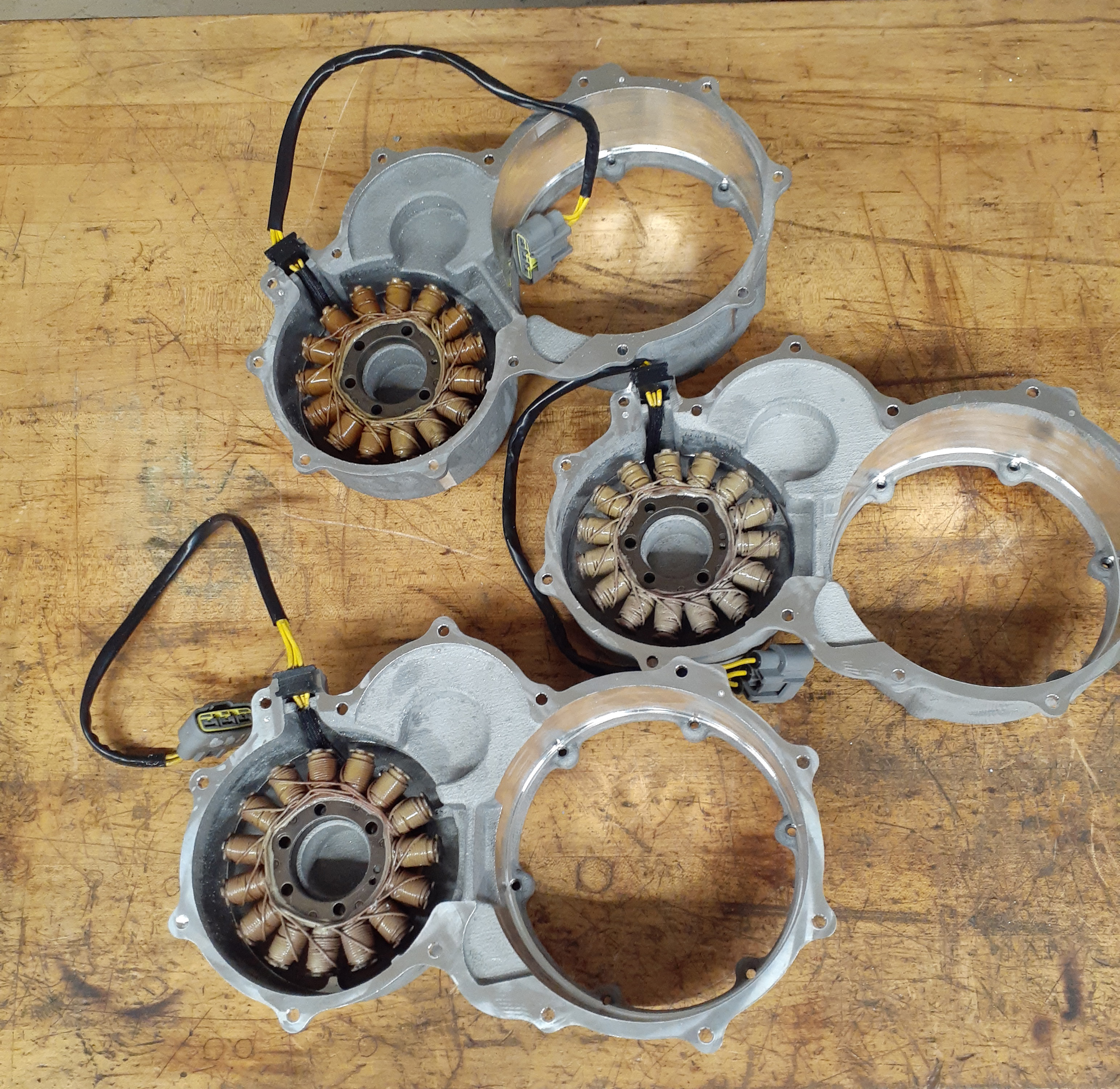
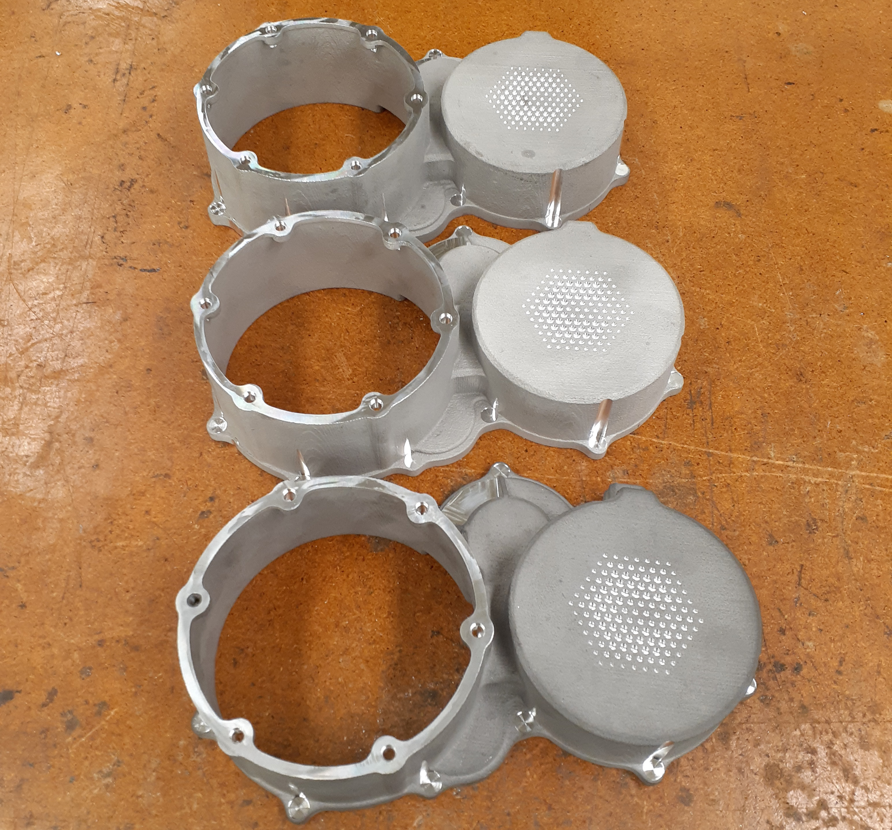
Repeat it all 2x and 3 right side covers are ready.
And now for those that made it this far, the money shot.
