

Setting up centers for the oil gear drive train was pretty straightforward, just copy center distances from the existing parts. The multi-stage starter gear train will be a bit different. In the ever delicate dance that is the mechanical engineer’s packing compromise, the starter gear train could not be used as-is. To get the tidiest overall engine package, I had to take the counter-intuitive step of making the starter gear drive system larger. With my unique middle counterbalance placement, space inside the engine was tight. I could swing the starter to the bottom or front of the engine with the OEM starter arrangement, but that would have increased the overall engine size. If I could stretch the starter drive train’s overall center distance, the small crankcase dimensions could be retained, with the relatively heavy starter motor being placed on top of the transmission and under the throttle body, helping centralize engine mass closer to the bike’s overall C of G.
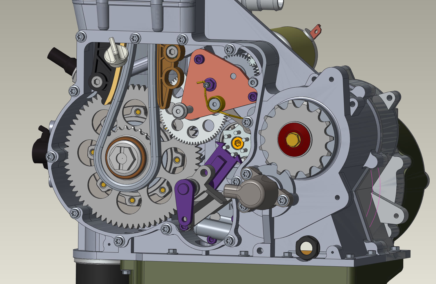
To accomplish this placement, an idler gear was added to the starter gear train immediately after the starter motor pinion. Being an idler gear, it would not change the overall reduction ratio, which is nice, but it would change the rotation direction, which usually is not nice. Since my middle counterbalance shaft placement’s primary purpose is to reverse the crank rotation, the added idler’s direction reversion then changes the previously unusable starter direction to the correct rotation direction. That’s two birds, one stone! Sweet!
Now that the overall layout was complete, the task switched to finding a spur gear to mesh with the unknown specification Ducati gears. Some quick calculations showed the gear to be a metric 1.0248 module. That’s a pretty odd size so it is most likely that it is a modified 1 Module gear. Gears in vehicle transmissions are not as standardized as you would expect. The constant fight between center distances, gear pitch/tooth count, and NVH considerations force gear designers to use standard hob profiles in non-standard ways. An easy example is when you want to fit 6 different gear ratios that all mesh on the same shaft.
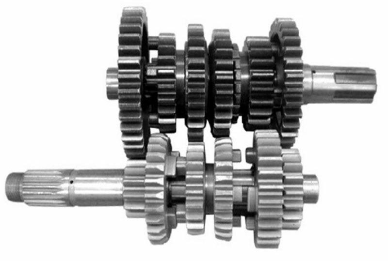
You want certain reduction ratios to compliment the engine’s power delivery curve. Only being able to make gears with an integral number of teeth limits the choices. If you wanted to stick to the same gear module, choices would be limited even further. The solution for production numbers is to under or overcut the gears so that the effective pitch diameter changes though the number of teeth remain the same. That allows gear designers more flexibility in fitting the desired ratios on a certain shaft center distance.
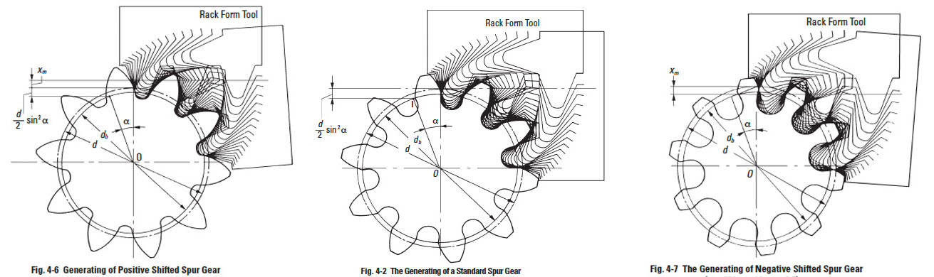
We’ve digressed a bit, but there is a good reason. This module modification technique was used on the starter gear train, so it might be difficult to make a gear to these non-standard specifications.
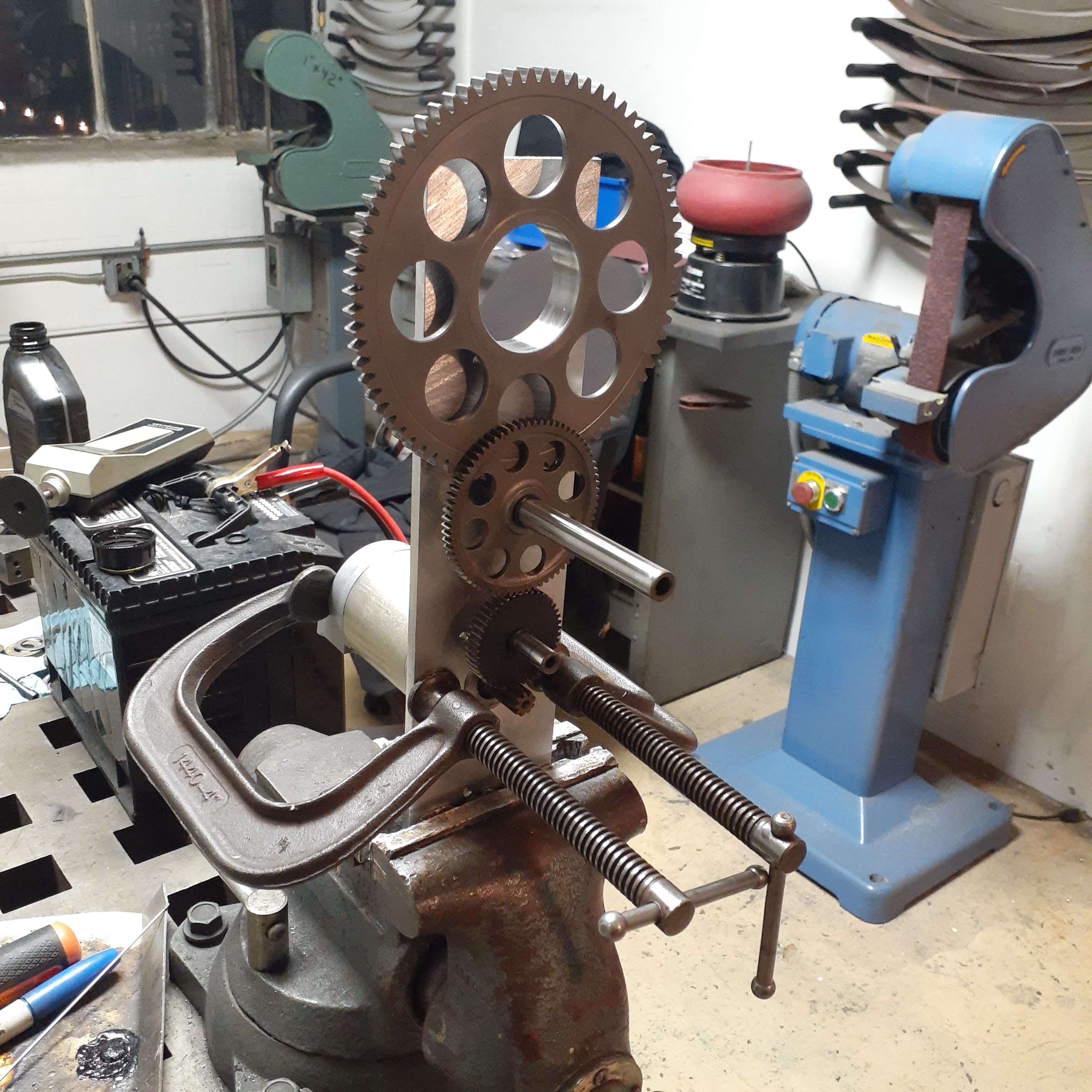
Enter the mc-chassis design mailing list, hosted by Michael Moore of eurospares.com fame. Michael’s lists are populated by an eclectic mix of motorcycle enthusiasts and fabricators that discuss a variety of motorcycle and non-motorcycle fabrication issues. A current topic is the use of woven polymer fibers used to stiffen archery bows for increased performance. Speed seems to be one of the central tenets of any post on the Chassis List. Anyway, one of the list members is Ian Drysdale, of the Drysdale V8 and 2x2x2 fame, among other projects. Ian runs a fabrication facility in Austrailia that from time to time does some gear work. Also being a motorcycle gearhead, Ian was the perfect person to ask how to match this gear. After providing a few tooth span measurements that he input into his GEARCAD program, Ian concluded that it was a simple modification of a standard 1.0M gear and that a standard gear might mesh well enough not to bother with a special. Luckily enough, Stock Drive Products happened to have the right module and tooth count gear in ground steel and in stock! And with the correct bore diameter! The gods are smiling! Or at least looking away. A small online transaction later and the gear was on its way. It arrived and was checked against the OEM ducati gears and passed the hand mesh test with flying colors, you couldn’t tell the difference between the OEM or aftermarket gear mesh. Now the task was to figure out what center distances were needed to get this all to spin nicely. The same baseplate technique process as the oil pump drive testing was done, but with the added step of needing to break out the Criteron boring head to make the 30mm and 58mm bores needed to to a mock-up.
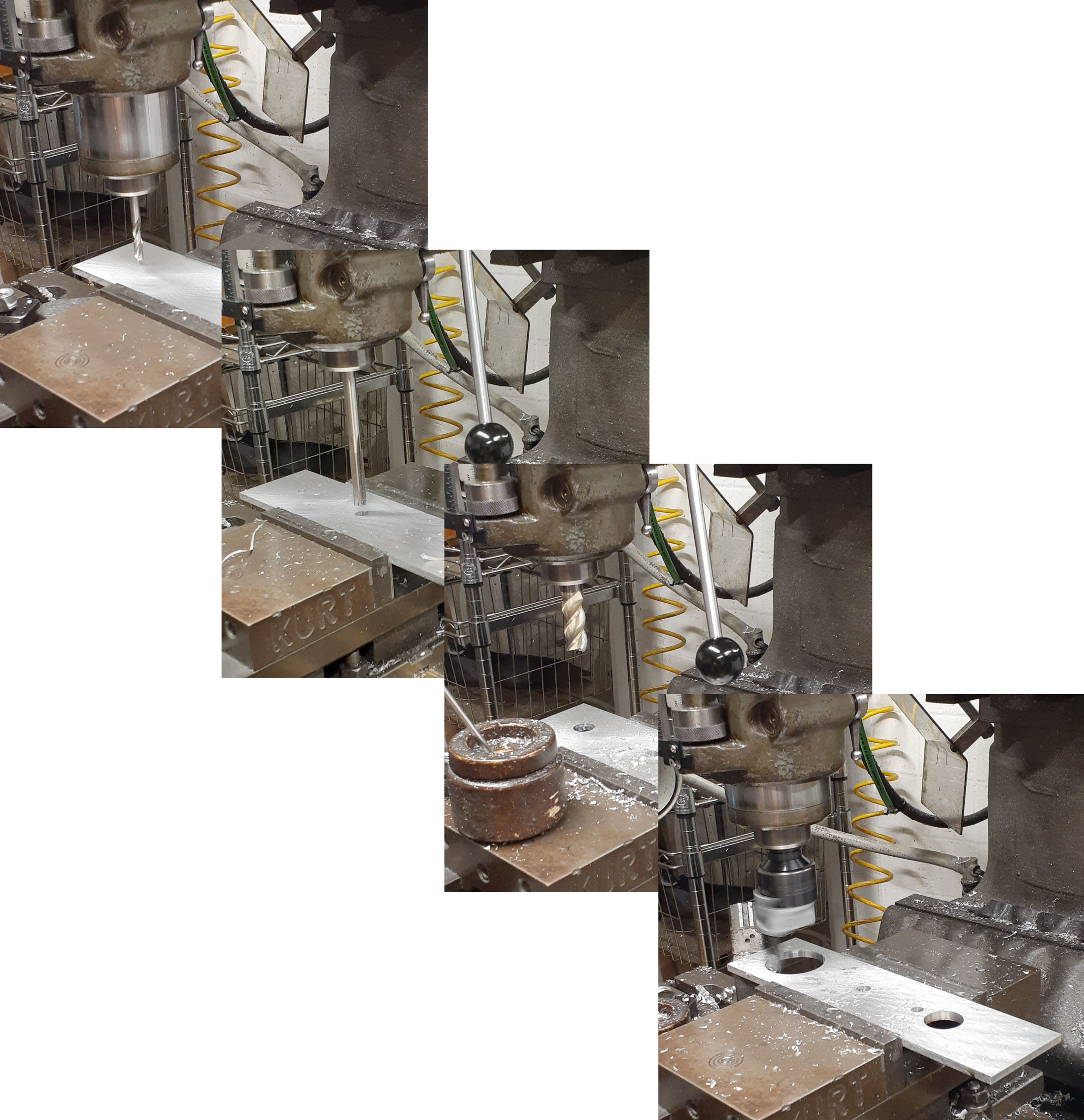
And a little video of a boring pass, its not really that exciting:
The first guess at the corrct center distance was close, but had significantly too much play on the mesh of the new idler gear to the OEM double gear.
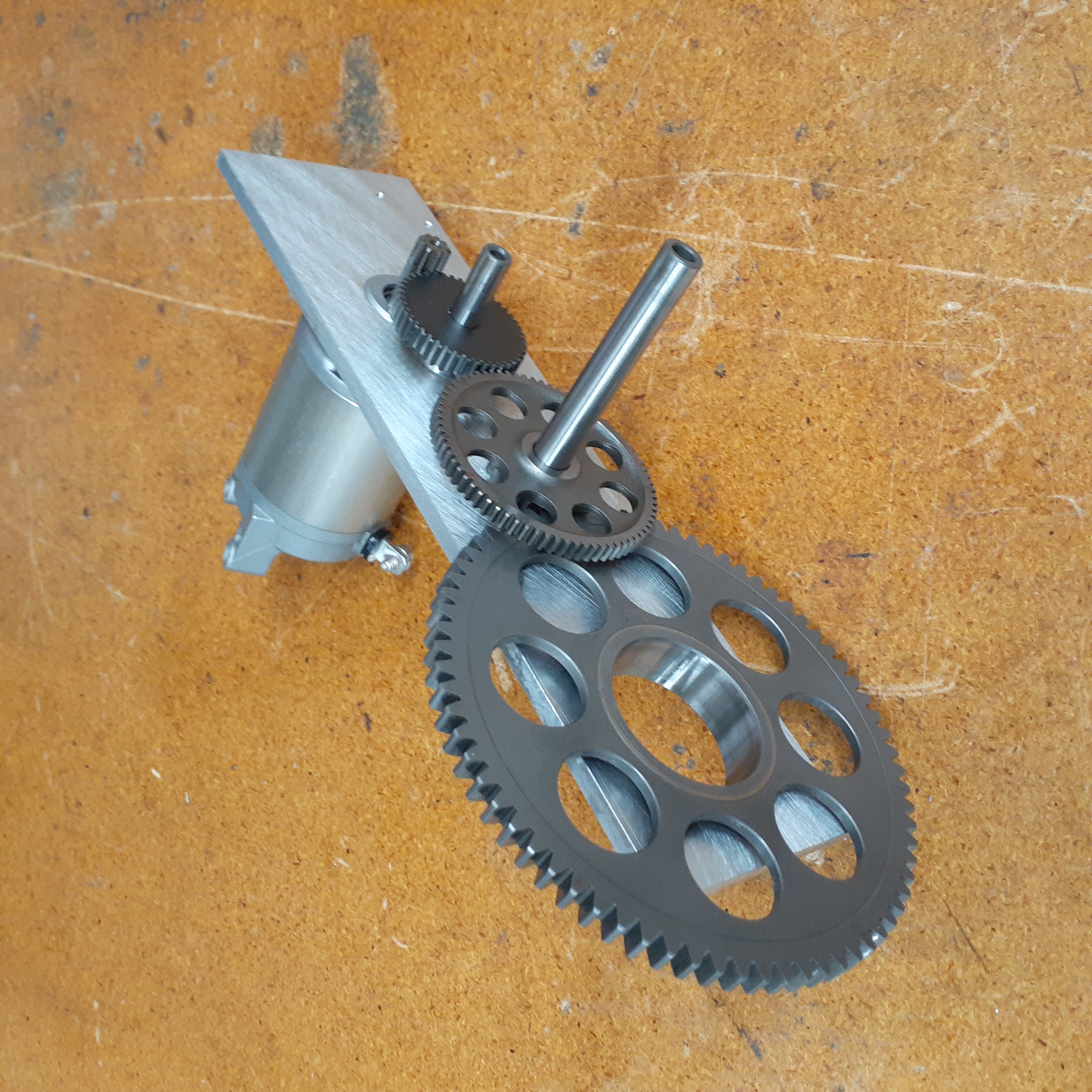
A few quick measurements and version two was successful. All of the gear meshes were within tolerance and there were no unusual noises when a demo run was done with the starter motor and a small car battery.
No weird noises and 250rpm cranking speed so all seems good.
Now on to the last verification stage, the crank/counterbalance/transmission shaft spacing. That should be coming soon.

great write-up and vg find of the ready made gear!!