There seems to be plenty of empty time these days so there is plenty of time to obsess over some bike design details! I’m sort of going a little stir crazy and am finding it hard to be really productive, so please bear with a scattershot blog post. I’ll be covering a bunch of stuff, from parts status to design details, to fabrication prep.
The last, last minute change is that we have decided to go from a 1299 piston/cylinder assembly which is a 116mm piston in a thin steel liner, to the 1199 piston cylinder assembly, which is a 112mm piston in a thicker aluminum liner. Seems that the 1199 is the basis for all the race development, like 2 ring pistons for less frictional drag. The lost 50cc of displacement will be more than made up for in less friction and better breathing.
Now that the important dimensions have now been set in stone, purchase orders have been issued and the bank account is cringing in submission:
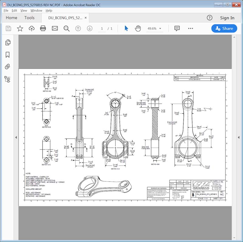
- custom length connecting rods from Carrillo
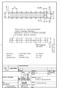
- custom length high performance roller cam chain from IWIS
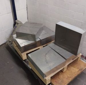
- 6061-T6511 aluminum blocks for crankcases
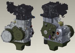
The engine CAD model is undergoing subtle refinements as time allows. Current state is good enough to freeze and start making chips but there seems to be no sense rushing things so I am revisiting details that, while satisfactory from a pure engineering perspective, just don’t have that elegant feel to the design solution. These areas are, of course, few and far in between. 😉
I have contracted with Curto-Ligonier Foundries to sand cast the two side covers and the oil sump in AZ91 magnesium. Curto will be providing all the feeding, gating and sprue design information which I will use to create cope and drag parts of the molds for sand casting.
The sand molds themselves will be 3D printed sand that the metal will be poured directly into. The sand molds will be 3D printed by Humtown Products. Brandon Lamoncha there has been a big help in gathering the various details needed for the process.
As the engine nears design completion, I can focus on the rest of the bike. Since the chassis and suspension are already fully detailed, I can progress to details like air intake routing, airbox, and electrical components.
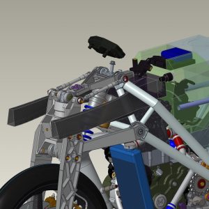
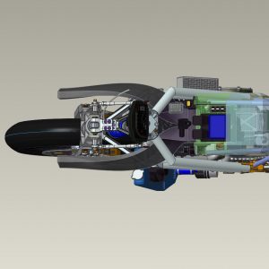
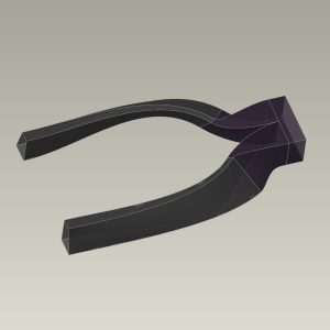
The dual air intake path threads through both small triangles formed at the crest of the frame then merges, has a filter mount, then enters the airbox. Its volume is approximately 9.5l, plenty big to tune the Helmholtz resonance frequency to help boost the mid-range power.
For the air runners, I determined the minimum air intake size, doubled it, then used Creo’s advanced 3d surfacing features to create duct with a curvature-continuous walls and a linearly increasing cross-sectional area. This helps slow the air from road speed to 0 with minimal losses, ensuring max static pressure. Even though ram air benefit is pretty small for a bike that can only do about 160mph, it makes sense to try to get what you can if it does not get in the way of something else that is more important.
The air intake system leaves plenty of room for a nice size filter at the front of the airbox housing. The various electronics modules (ECU, water pump control, coil, IMU, etc.) will live on to and around the base of the ram air ducts. I am not sure if there will be brackets molded into the ducts or a complex 3D printed housing that has a few discrete mounting points. Those details have a minor enough impact on the surronding parts that I can push them back until the first test assembly phase, where details like this are best resolved.
That’s about it for now. Forthcoming posts will cover the sand mold design process and the resultant castings, and the start of crankcase and crankshaft machining.
Hope you are all staying sane during this craziness.


