Now that I’m done with the pockets on the primary drive gear there is some empty space on the mill bed so I’ll get in come clutch cover machining in while the setup is available.
After machining the 4340 steel going back to aluminum is a pleasure. The 4340 steel is a high strength steel that requires a rigid setup with speeds (how fast the spindle/cutting tool spins around) and feeds (how fast the cutting tool is advanced through the material) about 1/3 that of aluminum. If cutting aluminum can be compared to a hot knife going through butter you can describe cutting high strength steel as a butter knife going through steak. A tough stringy steak, not a nice tender filet mignon. One that quickly dulls even the hardest coated carbide cutting tools.
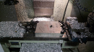
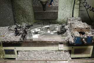
Back to the topic at hand, cutting aluminum. As usual we start with a large flat plate clamped to the table and gradually whittle away all the unnecessary material.
Careful clamping and slightly thicker stock will allow me to leave a thin bridge of material around the perimeter making it easy to clamp and machine without clever fixtures.
All the programming was correct and this operation went off without a problem.
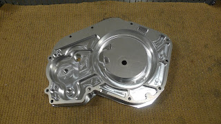
The large circular island in the middle of the part is where the clutch will go. This island was left to allow me to use the hole as an initial clamping point for the second mill operation. When the last facing operation is done the round dropout will become scrap.
I ran two parts and checked fit of the starter shafts and gears that this cover houses and everything fit properly.
I now have to program and run the fixture plate for the second mill operation then program and run the front side of both parts. That will finish the part and allow me to start mocking up the starter gears and right hand side engine components. Hopefully I can get to that in the coming week and put up another post.


What Cad software has a better scope for a job? in mechanical design software? sincere answers please!?
Solidworks
Pro-Engineer all the way.